 |
2-2: Circuit Creation |
|
|
2-2: Circuit Creation |
|
Node creation is done by selecting a node from the component menu on the left, or by using one of the New commands of the Edit menu (New Cell Instance, New Analog Part, New Spice Part, New Pure Layer Node, New Special Object). These commands then wait for a click in the editing window to place the component. The location of the cursor is aligned to the nearest grid unit, and this adjustment can be controlled with the Alignment Options... command of the Windows menu.
When placing a node, the cursor points to the grab point of the newly created node. By default, this is the center (for primitives) or the lower-left corner (for cell instances). Primitive nodes can use the lower-left corner as the grab-point by unchecking the "Center-based primitives" checkbox in the Selection Options... subcommand of the Selection command of the Edit menu. When this is unchecked, the Get Info dialog shows the node's lower-left position, rather than its center.
Cell instances can change their grab-point by placing a Cell-Center node inside of their layout (see Section 3-3).
As the introductory example showed, arcs are created by clicking the creation button. This can actually function in two different ways, depending on what is highlighted.
If one node is highlighted, segment wiring is done, in which an arc is drawn from the highlighted node to the location of the cursor. If there is nothing at that location, a pin is created, and it is left highlighted. Using the creation button again runs an arc from the pin to another location. By clicking and holding the creation button, you can see the path that the new arc will follow.
If the cursor is over another object when this command is issued, the new wire attaches to that object. To disable this "attach" feature of segment drawing, use the wire button instead of the creation button.
In general, all wiring operations should be done by clicking and holding the creation button, then moving the cursor until the intended wiring is shown, and finally releasing. This is recommended because wiring is quite complex and can follow many different paths.
The other way that the creation button can operate is two-point wiring, in which two nodes are highlighted and one or more arcs are created to connect them. Highlighting of these two nodes is done by clicking the selection button over the first one, and then using the toggle select button on the second. Note that if the second node is obscured by other objects, you can cycle through the objects under the cursor with the toggle select another button. Once the two nodes are highlighted, use the creation button to wire them together. Note that the highlighted ports on the selected nodes are important: arcs will run between them, so they must be compatible in their wiring capabilities.
| Two-point wire creation first attempts to run a single arc. Generally, this can happen only if the ports are lined up accurately. Failing single arc placement, an attempt is made to connect with two or three arcs and intermediate nodes. The determination of arc location depends upon the position of the cursor when the creation button is clicked. If the cursor is inside of the area defined by the two components, the connection will make a "Z" bend through the cursor. If the cursor is to one side of the components, the connection will make a "U" bend through the cursor location. Finally, if the cursor is in a corner outside of the components, the connection will make an "L" bend towards the cursor. | 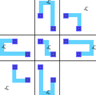 |
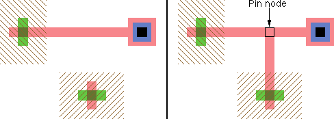 | In addition to running an arc between two nodes, you can also use arcs as the starting or ending point of arc creation. If it is sensible, the creation command actually uses one of the nodes on an end of the selected arc. However, if the connection falls inside the arc, it is split and a new node is created to make a "T" connection. |
Whenever an arc is created, the system makes a clicking sound. The sound is a single click for one arc, a double-click for two arcs, and a triple-click for three or more arcs. To disable this sound, use the General Options... subcommand of the User Interface command of the Info menu and uncheck "Click sounds when arcs are created".
When connecting between two objects that are on different layers, Electric will insert a via to change layers. Only one via can be inserted. Thus, you can wire from a metal-1 pin to a metal-2 pin, and a single via will be created; but you cannot wire from a metal-1 pin to a metal-3 pin, because that would require two vias. When a via is inserted, it is placed closest to the "destination" node (or farthest from the original node).
The width of a new arc is automatically chosen according to a number of factors. The default width is set in the New Arc Options... command of the Arc menu. If there are other arcs of this type already connected to the new one, and they are wider than normal, then the new arc will use that width.
Note that all arcs overlap their endpoint by half of their width, so very wide arcs may overlap their destination with too much geometry. You can turn off this overlap by using the Ends-extend command of the Arc menu.
| An unusual circuit creation command is the Insert Jog In Arc command of the Edit menu. This command inserts a jog in the highlighted arc by replacing it with three new arcs. Two of the new arcs run to the location of the cursor, and the third arc is perpendicular to them, connecting the ends at the cursor location (initially it has zero length). Once the jog is inserted, either half of the arc may be moved without affecting the other half, and the perpendicular arc will keep the circuit connected. | 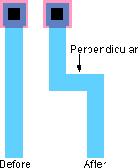 |
Beginning users often leave many extra pins in their circuits. With the Cleanup Pins subcommand of the Cleanup Cell command of the Edit menu, these pins are automatically removed from your circuit, leaving a cleaner network. The command does other pin organizations, such as making sure that text on these pins is located correctly, identifying zero-sized pins, and identifying oversized pins. The Cleanup Pins Everywhere command does this function for all cells at once.
 |
Previous |  |
Table of Contents | Next |  |