Chapter 7: Technologies
 |
7-3: I/O Control
7-3-3: GDS Control |
|
|
GDS II (also called "Stream" format) is used as an interchange between design systems and fabrication facilities.
For information on reading and writing GDS, see
Section 3-9-2 and
Section 3-9-3, respectively.
In GDS files, there are no names for each layer, just a pair of numbers (the layer number and type).
It is important that Electric know how these values correspond with layers so that it can properly
read and write GDS files.
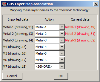
You can import and export the correspondences by using the GDS Map File... command
(in the File / Import and File / Import menus).
|  |
If a GDS file makes reference to cells that are not defined in that file,
Electric will look in any existing libraries to see if those cells can be found.
You can also use the GDS Preferences
(in menu File / Preferences..., "I/O section, "GDS" tab) to edit the GDS numbers and
control other aspects of GDS input and output.
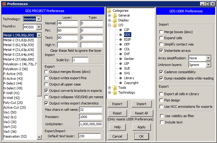
Project Preferences
The left side of the dialog shows the Project Preferences which control the mapping
of GDS layer numbers to Electric layers.
The list on the left shows all of the Electric layers in the current technology.
By clicking on a layer name, its GDS numbers are shown in the top-right and can be edited.
GDS numbers come in a few different variations:
- Normal for regular geometry.
- Pin for exports.
- Text for export names and special GDS text.
You can use the Add GDS Text command (in menu Edit / Text) to add text to the selected object.
That text will be emitted using this "Text" layer number.
- High V for high voltage layers.
You can use the Add HV GDS Text command (in menu Edit / Text) to add high-voltage text to the selected object.
That text will be emitted using this "High V" layer number.
To ignore a layer, clear the layer field (it is not sufficient to set it to zero...it must be blank).
This dialog element applies to the import of GDS:
- "Scale by".
This scales the GDS by the given factor when read from disk.
These dialog elements apply to the export of GDS:
-
"Output merges Boxes".
This controls the merging of adjoining geometry.
It is an issue because of the duplication and overlap that occurs wherever arcs and nodes meet.
The default action is to write each node and arc individually.
This makes the file larger because of redundant box information,
however it is faster to generate and uses simpler constructs.
If you check this item,
all connecting regions on the same layer are merged into one complex polygon.
This requires more processing, produces a smaller file, and generates more complex constructs.
-
"Output writes export Pins".
This controls whether pins are written to the GDS file for each export.
If checked, and there is a valid pin layer, then it is written.
-
"Output all upper case".
This controls whether the GDS file uses all upper case.
The default is to mix upper and lower case, but some systems insist on upper-case GDS.
-
"Output converts brackets in exports".
This controls whether the square brackets used in array specifications should be converted (to underscores).
Some GDS readers cannot handle the square bracket characters.
- "Output collapses VDD/GND pin names".
Requests that all names with the form "vdd_NNN" or "gnd_NNN" (where "NNN" is digits) be merged into a single power or ground signal
called "vdd" or "gnd".
- "Output writes export characteristics".
Requests all GDS "pins" (Electric exports) contain characteristics (input, output, etc.)
This may be incompatible with some versions of GDS so it can be disabled.
-
"Max chars in cell name".
This limits the number of characters in a cell name.
Names longer than this are truncated, and adjusted to ensure uniqueness.
- "Precision" and "Units/meter" define the scaling information written to a GDS file.
The Precision is the number of units available and the Units/meter defines the size of a unit.
The default Units/meter is a billion, meaning that the unit size is 1 nanometer.
Note that some small feature-size technologies may require a larger Units/meter field.
If GDS Export encounters precision errors, you will be asked to increase this value.
At the bottom is a setting for both export and import:
- "Default text layer".
This is the layer number to use for text.
When exports are being written, and there is a text layer number associated with the appropriate Electric layer,
then that layer number is used instead of this default number.
User Preferences
These dialog elements are available on the right side (the GDS User Preferences) for import control:
- "Merge boxes (slow)".
This requests GDS input to combine overlapping boxes into complex polygons.
It takes more time, but produces a more compact database.
- "Expand cells".
This controls whether cell instances are expanded or not in the Electric circuit.
By default, cell instances are not expanded (they appear as a simple box).
If you check this item, cells are expanded so that their contents are displayed.
Expansion of cells can always be changed after reading GDS by using the subcommands of the Expand Cell Instances
and Unexpand Cell Instances commands of the Cells menu.
- "Simplify contact vias".
This requests GDS input to find combinations of metal and via cuts and replace them with Electric contacts.
It takes time, and may simplify some GDS.
- "Instantiate arrays".
This controls whether or not arrays in the GDS file are instantiated.
By default, arrays are instantiated fully, but this can consume excessive amounts of memory if there are large arrays.
If you uncheck this item, only the upper-left and lower-right instance are actually placed.
- "Array simplification".
This controls the simplification of special "array reference" objects in GDS.
When an array of cell instances is found, and each cell instance contains a single piece of geometry,
Electric can simplify the array specification so that a single pure-layer node is created instead
of an array of instances.
This pure-layer node has outline information that covers each of the arrayed objects
(see Section 6-10-1 for more on outlines).
This preference can be set to "None" (no simplification of array references is used),
"Merge individual arrays" in which the above simplification is performed,
and "Merge all arrays" in which multiple array references are combined so that a single pure-layer node
is place for each layer in the cell, regardless of the number of array references that are used.
This last choice can produce highly-complex pure-layer nodes, but is fastest and uses the least amount of memory.
- "Unknown layers".
This controls how unknown layers in the GDS file are treated.
The default is "Convert to DRC Exclusion layer" which creates an orange DRC-Node wherever an unknown layers appears.
Each DRC-Node is tagged with the unknown layer number.
If you set this to "Ignore", the unknown layers are simply ignored.
A final choice is "Convert to random layer" which picks a different layer in the technology for each unknown GDS layer number.
This allows the distinction between layers to be seen, even if the correct layer associations are not known.
- "Cadence compatibility".
This forces a GDS import to do things that assume the GDS has come from a Cadence system.
Export locations are expanded to cover the geometry on which they reside,
because Cadence allows connections to be elsewhere on the layer..
Also, Cadence style bus delimeters (<>) are converted to Electric style ([]).
- "Dump readable data while reading" is a way to debug GDS files.
When this is checked, the GDS data is written to a text file during import,
allowing you to see what is in the file.
These dialog elements are available on the right side (the GDS User Preferences) for export control:
- "Export all cells in Library".
Normally, only those cells that are part of the current hierarchy are written to the GDS.
The current hierarchy is the current cell and all of its sub-cells.
When this is checked, every cell in the library is written.
This is useful when writing out standard cell libraries.
- "Flat design". This fully-instantiates the circuit (flattens it) before writing.
Output files may be much larger because there is no hierarchy.
- "Use NCC annotations for exports".
The network consistency checker (NCC)
allows special circuit annotations to join two networks.
For example, two separate power networks may be joined higher in the circuit hierarchy,
and the NCC needs to know this at the current level of design.
This checkbox requests that the NCC annotations be used when exporting GDS.
It enables external circuit analysis programs (such as Assura) to properly understand the circuit connectivity.
Specifically, when this is checked, all of a layout cell's
exports which are linked by the NCC exportsConnectedByParent annotation will be given the same GDS pin text
(see Section 9-7-4 for more on NCC annotations).
These dialog elements are available on the right side (the GDS User Preferences) for export and import control:
- "Use visibility as filter" uses the current layer visibility as a filter for what gets imported or exported.
For more on layer visibility, see Section 4-5-3.
- "Include text".
Text annotations in the GDS file can often clutter the display, so they are ignored during input.
If you check this item, annotation text will be read and displayed.


