
6-10-1: Introduction to Outlines
Chapter 6: Advanced Editing
|
6-10: Outlines 6-10-1: Introduction to Outlines |
|
|
For some primitive nodes, it is not enough to rotate, mirror, and scale. These primitives can to be augmented with an outline, which is a polygonal description. There are quite a few primitive nodes that make use of outline information. The MOS transistors use the outline to define the gate path in serpentine configurations (see Section 7-4-1). The Artwork technology has nodes that use outline information: Opened-Solid-Polygon, Opened-Dotted-Polygon, Opened-Dashed-Polygon, Opened-Thicker-Polygon, Closed-Polygon, Filled-Polygon, and Spline (see Section 7-6-1). For arbitrary shapes on arbitrary layers, use the pure-layer nodes in the IC layout technologies. The pure-layer nodes are found under the "Pure" entry in the component menu. For example, the node called "Metal-1-Node" in the CMOS technologies looks like a rectangle of the Metal-1, until you add outline information. With an outline, this node can take any shape. It is even possible to have multiple disjoint outlines in a single pure-layer node (users cannot create this situation, but some tools such as GDS import can). | 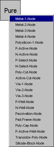 |
Because pure-layer nodes are unusual, it is useful to be able to identify them. Use the Show Pure Layer Nodes command (in menu Edit / Cleanup Cell) to highlight all of them in the current cell. If pure-layer nodes overlap each other, use Show Redundant Pure Layer Nodes to identify those that are enclosed by others and, therefore, are redundant.
 |
Previous |  |
Table of Contents | Next |  |