10-4: Behavioral Models (ALS) |
10-4: Behavioral Models (ALS) |
To create (or redefine) a primitive's behavior, simply create the "netlist" view of the cell with that primitive's name. Use the Edit Cell... command of the Cells menu and select the "netlist-als-format" view. For example, to define the behavior of an ALU cell, edit "alu{net-als}", and to redefine the behavior of a two-input And gate, edit "and2{net-als}". The compiler copies these textual cells into the netlist description whenever that node is referenced in the VHDL.
A library that contains only behavioral models can be built and kept separately from the current library. To identify that library as the location of behavioral models, use the Select Behavioral Library... subcommand of the VHDL Compiler command of the Tools menu.
The netlist format provides three different types of defining entities: model, gate, and function. The model entity describes interconnectivity between other entities. It describes the hierarchy and the topology. The gate and function entities are at the primitive level. The gate uses a truth-table and the function makes reference to C-coded behavior (which must be compiled into Electric, see the module "simalsuser.c"). Both primitive entities also allow the specification of operational parameters such as switching speed, capacitive loading and propagation delay. (The simulator determines the capacitive load, and thus the event switching delay, of each node of the system by considering the capacitive load of each primitive connected to a node as well as taking into account feedback paths to the node.)
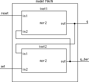
A sample netlist describing an RS latch model is shown below:
 |
The model declaration for the figure is as follows:
      model main(set, reset, q, q_bar)
      inst1: nor2(reset, q_bar, q)
      inst2: nor2(q, set, q_bar)
The gate description of the nor2 is as follows:
      gate nor2(in1, in2, out)
      t: delta=4.5e-9 + linear=5.0e-10
      i: in1=L in2=L   o: out=H@2
      i: in1=H         o: out=L@2
      i: in2=H         o: out=L@2
      i:               o: out=X@2
|
When combined, these entities represent a complete description of the circuit. Note that when a gate, function, or other model is referenced within a model description, there is a one-to-one correspondence between the signal names listed at the calling site and the signal names contained in the header of the called entity.
| Previous | Table of Contents | Next |