 |
6-10: Outline Editing |
|
|
6-10: Outline Editing |
|
For some primitive nodes, it is not enough to rotate, mirror, and scale. These primitives can to be augmented with an outline, which is a polygonal description. The Outline Edit subcommand of the Special Function command of the Edit menu is used to create, delete, and move individual points in a node's outline.
There are quite a few primitive nodes that make use of outline information. The MOS transistors use the outline to define the gate path in serpentine configurations (see Section 7-4). The Artwork technology has nodes that use outline information: Opened-Solid-Polygon, Opened-Dotted-Polygon, Opened-Dashed-Polygon, Opened-Thicker-Polygon, Closed-Polygon, Filled-Polygon, and Spline (see Section 7-7).
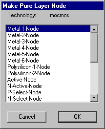 | For arbitrary shapes on arbitrary layers, use the pure-layer nodes in the IC layout technologies. The pure-layer nodes are those in the New Pure-Layer Node... command of the Edit menu. For example, the node called "Metal-1-Node" in the CMOS technologies looks like a rectangle of the Metal-1, until you add outline information. With an outline, this node can take any shape. |
| To manipulate outline information on the currently highlighted node, use the Outline Edit subcommand of the Special Function command of the Edit menu. After issuing this command, the window is highlighted with a blue border. In this mode, the selection button is used to select and move a point on the outline, and the creation button adds a new point after the selected one. You can also use the left and right arrow keys to move around the outline. The Erase command of the Edit menu changes to Erase Point and deletes the highlighted outline point (so does the Delete key). The Rotate and Mirror commands change to Rotate about Point and Mirror about Point which allow the entire node to pivot about the currently selected point. Finally, the Get Info command of the Info menu changes to Get Outline Info and displays a dialog which allows precise manipulation of the data. | 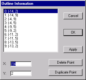 |
When done editing the outline, use the Exit Outline Edit subcommand (in the same location as Outline Edit was in the Special Function command of the Edit menu).
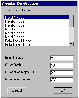 |
To generate a doughnut shaped outline, use the Annular Ring
subcommand of the New Special Object command of the Edit menu.
This dialog prompts for a layer to use and an inner and outer radius for the annulus.
By default, it is made as a full circle (360 degrees), but this can also be changed.
Finally, the number of line segments used in the construction can be set,
allowing for smoother or coarser shapes.
 |
|
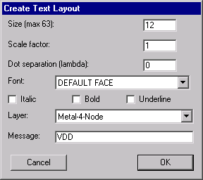
To generate text-shaped outline,
use the Text (layout)... subcommand of the New Special Object command of the Edit menu.
This dialog prompts for text and a layer to use as well as the size, scale, font, and style.
A nonzero dot separation causes each pixel of the text to be placed separately (some design rules need this).
 |  |
 |
Previous |  |
Table of Contents | Next |  |