 |
6-9: Networks |
|
|
6-9: Networks |
|
Whenever a port on a node is selected, the highlighting indicates the entire network that is connected to that port. Another way to see an entire network is to use the Show Network subcommand of the Network command of the Tools menu. This will highlight all arcs on the currently selected networks. If the design is very dense, you can select one or more networks by name with the Select Network... subcommand of the Selection command of the Edit menu.
The Resistor can be treated as a connecting or nonconnecting node. By default, it does not connect the networks on its two ends, so identification of the extent of a network ends at the resistor. To ignore resistors and treat them as wires, use the Network Options... subcommand of the Network command of the Tools menu and check "Ignore Resistors". Then highlighted networks will pass through them. See section Section 7-6 for more on resistors.
There are many commands that can be used to get information about the networks in a cell:
Network names are derived from export names and arcs that are named in a cell. The name given to an export is the network name for all arcs connected to that export. Similarly, the name given to an arc (by setting the name field in the Get Info command) becomes the name of the network for all connected arcs. You can rename a network by changing the specific export or arc, or by using the Rename Network... command of the Info menu.
Two phenomena can occur in network naming: a network can be multiply named, and it can span disjoint circuitry. A network has multiple names when two or more connected arcs or exports are named with different names. For example, if you make an export on a contact node and call it "clock", then you select an arc connected to that contact node and name it "sig", the circuitry will be on the network "clock/sig."
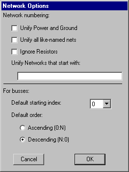 | The other phenomenon of network naming is that a single network can include unconnected parts of the circuit. This happens when arcs in unconnected parts of the circuit are given the same name. This causes the two arcs to be implicitly joined into one network. Because this network naming phenomena is most commonly used in schematics, the unification of like-named networks only happens in cells with the "schematic" view. To cause this same effect in all views (such as "layout"), use the Network Options... subcommand of the Network command of the Tools menu and check the "Unify all like-named nets" item. |
You can also use this dialog to request that all networks that start with a particular set of letters should be unified. For example, if the "Unify Networks that start with" field is set to "clk", then the networks "clk01" and "clkExtra" will be merged into a single network. Multiple merges can be specified, separated by spaces. For example, if the field is "pwr gnd" then all nets starting with "pwr" will be merged, and all nets starting with "gnd" will be merged.
When busses must be automatically generated (during netlisting, for example) the bus indices can be set to start at 0 or 1, and they can ascend or descend.
The Bus arc of the Schematics technology is a special arc that can carry multiple signals. When giving a network name to Bus arcs, it is possible to specify complex bus names. Bus names can be lists (for example, "clock,in1,out" which aggregates 3 singals into a 3-wide bus) or they can be arrays (for example, "A[0:7]" which defines an 8-wide bus). Arrays indexes can be individual values, or ranges of values (for example, the bus "b[0],c[3,5],d[1:2],e[8:6]" is an 8-wide bus with signals in this order: b[0], c[3], c[5], d[1], d[2], e[8], e[7], e[6]). Finally, it is possible to use symbolic indices in bus naming (for example, the bus "r[x,y]" defines a 2-wide bus with the signals r[x] and r[y]).
When a bus is unnamed, the system determines its width from the ports that it connects. Some tools (such as simulation netlisters) need to name everything, and so must give names to these unnamed busses. You can control the way that these busses are numbered by setting the "Default starting index" field in the Network Options... dialog. You can also select whether the numbering should go up or down.
Individual wires that connect to a bus must be named with names from that bus. As an aid in obtaining individual signals from a bus, the Rip Bus Signals subcommand of the Network command of the Tools menu will automatically create such wires for the selected bus arc.
Besides using array names on busses, you can also give array names to schematic nodes. Netlisters will create multiple copies of that node, named with the individual elements of the array.
Identification of a power network is done by finding:
By default, supply networks defined with the Power and Ground nodes of the Schematic technology are combined into one network. This means, for example, that two arcs, each connected to a separate Ground node, appear on the same network regardless of their actual connectivity in the circuit.
Although this unification is the proper thing to do for schematics, it is not always proper for IC layout. For example, in MOS technologies, two ports exported with the "power" characteristic are not on the same net unless they are actually connected (there may be multiple power rails that do not connect). As a circuit debugging aid to ensure that power and ground networks are properly connected, Electric can be instructed to unify power and ground networks in ALL technologies, regardless of their actual connectivity. The Network Options... subcommand of the Network command of the Tools menu has the "Unify Power and Ground" item which causes all power and ground networks to be combined. This unification of all supply rails can be disabled by unchecking the menu entry. By highlighting power and ground networks with and without this option, designers can see whether all of their supply rails are fully connected.
The Validate Power and Ground subcommand of the Network command of the Tools menu checks all power and ground networks in the circuit. Any power or ground networks that are named according to the prefixes listed above must have the proper characteristics. If, for example, a power network is called "gnd007", then it will be flagged by this command.
When wiring an IC layout, the only way to get a signal from one point to another is to physically place the wires. Signals that span a large circuit, such as power and ground, must be carefully wired together at each level of the hierarchy.
In schematics, however, it is often the case that a signal is used commonly without specially being wired or exported. Examples of such signals are power, ground, clocks, etc. The power and ground signals can be established in any schematic with the use of the Power and Ground nodes. To create another such signal, use the Global node of the schematics technology.
The Global node is diamond-shaped, and it has a name and characteristics similar to exports (input, output, etc.) All signals with the same global name are considered to be connected when netlisting occurs. Thus, the Global symbol can be used to route clock signals, as well as to define multiple power and ground rails. Note that with multiple power and ground rails, only one of them is the true "power and ground" as defined by the Power and Ground symbols. All others, declared with Global nodes, are not true power and ground signals, but are simply globals.
Not all netlisters in Electric use Global signals. At this time, only SPICE, Verilog, IRSIM, and the Network Consistency Checker make proper use of this feature.
 |
Previous |  |
Table of Contents | Next |  |