12-6: The View Menu |
12-6: The View Menu |

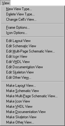
Each cell has a view associated with it. Although Electric defines a standard set of view types (layout, schematic, icon, skeleton, simulation-output, VHDL, document, and many netlist formats) it is possible to define new view types (for example, "fast layout") and to assign these views to cells. Special commands switch between the different views of a cell. This menu also controls the display of schematic frames. Finally, there are commands that automatically generate new cells of a different view type.
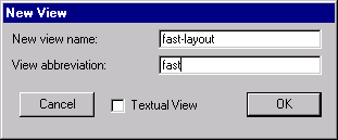
| This command creates a new type of view for cells. You will be prompted for the name of the view and an abbreviation to use in cell names. The abbreviation appears in curly brackets after the cell name, for example MyAdder{fast}. |  |
This command deletes a view type. There cannot be any existing cells with this view. Also, it is not possible to delete the basic view types that are defined by Electric.
This command changes the view type of the current cell. The cell name remains the same, but the view changes. You will be prompted for the new view. Note that this is one of the few commands in Electric that is NOT undoable.
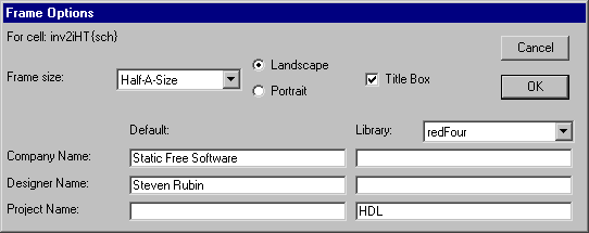
This command allows you to control the drawing of a frame in the current cell. You can choose among 6 frame sizes ("Half-A", "A", "B", "C", "D", or "E") and also whether they are wider (landscape) or taller (portrait).
| In addition, you can provide information that will be displayed in the corner of the frame (currently, only the company name, project name, and designer name). |  |
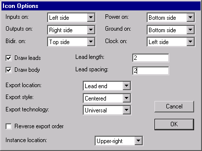
| This dialog controls how icons are created from schematics. For each type of port in the schematic, you can control on which of the four sides of the icon the port will appear. You can also control the location and order of ports and the style of their text. You can control whether the icon has a body or leads for each port, the size and spacing of the leads, and which technology to use for the export connections. Finally, you can control where the newly created icon's instance will appear in the schematic. |  |
If the current cell has an associated layout view, a new window is created to display that view.
If the current cell has an associated schematic view, a new window is created to display that view.
If the current cell has an associated multi-page schematic view, a new window is created to display that view. You will be prompted for the page number. Multi-page schematics are described with the "pN" view type, where "N" is the page number. For example, to edit page 6 of cell "happy", look for the cell called "happy{p6}".
If the current cell has an associated icon view, a new window is created to display that view.
If the current cell has an associated VHDL view, a new window is created to display that view. Note that the VHDL view is a textual view, so you will now be using a text editor. See Section 4-10 for more on text editing.
If the current cell has an associated documentation view, a new window is created to display that view. Note that the documentation view is a textual view, so you will now be using a text editor. See Section 4-10 for more on text editing.
If the current cell has an associated skeleton view, a new window is created to display that view.
If the current cell has an associated other view, a new window is created to display that view. You will be prompted for the view type that you wish to edit.
This command creates a new layout cell of the cell in the current editing window (or a new version of the layout view if one already exists). It is presumed that the current cell is a layout or schematic view and that the new cell is layout in a different but similar technology. You will be prompted for the new technology.
This command creates a new schematic cell of the cell in the current editing window. It is presumed that the current cell is a layout view. If there is already a schematic view of this cell, a new version of the schematic is created.
This command creates a new page of a multi-page schematic cell of the cell in the current editing window. You will be prompted for the page number. Multi-page schematics are described with the "pN" view type, where "N" is the page number. For example, to edit page 6 of cell "happy", look for the cell called "happy{p6}". If there is already a multi-page schematic view of this cell with the requested page number, a new version of that page's cell is created.
This command creates a new icon cell of the cell in the current editing window. The new cell has the same ports but a black-box look with input ports on the left, outputs on the right, power and ground on the top, and clock lines on the bottom. The Icon Options command controls the generation of icons.
This command creates a new VHDL cell (a textual view) of the cell in the current editing window. All subcells of the current cell are also translated to VHDL, and their descriptions are stored in views of the subcell. If "VHDL stored in cell" is unchecked (in the VHDL Options... subcommand of the VHDL Compiler command of the Tools menu), all VHDL will be written to disk.
This command creates a new Documentation cell (a textual view) of the cell in the current editing window.
This command creates a new skeleton cell of the cell in the current editing window. The new cell has the same size and ports, but none of the internal layout.
This command creates a new cell of the cell in the current editing window. You will be prompted for the view type of the new cell.
| Previous | Table of Contents | Next |