 |
9-8: Pad Frame Generation |
|
|
9-8: Pad Frame Generation |
|
The Pad Frame generator reads a disk file and places a ring of pads around your chip. The pads are contained in a separate library, and are copied into the current library to construct the pad frame.
The format of the pad frame disk file is as follows:
celllibrary LIBRARYFILE [copy] | ; Identifies the file with the pads |
facet PADFRAMECELL | ; Creates a cell to hold the pad frame |
core CORECELL | ; Places your circuit in the center of the pad frame |
align PADCELL INPUTPORT OUTPUTPORT | ; Defines input and output ports on pads |
place PADCELL [GAP] [PORTASSOCIATION] | ; Places a pad into the pad frame |
rotate DIRECTION | ; Turns the corner in pad placement |
The file must have exactly one celllibrary and cell statement,
as they identify the pad library and the pad frame cell.
If the celllibrary line ends with the keyword copy,
then cells from that library are copied into the library with the pad ring (by default, they are merely instantiated,
creating a cross-library reference to the pads library).
The file may have only one core statement to place your top-level circuit inside of the pad frame.
If there is no core statement,
then pads are placed without any circuit in the middle.
The align statement is used to identify connection points on the pads that will be used for placement.
Each pad should have an input and an output port that define the edges of the pad.
These ports are typically the on the power or ground rails that run through the pad.
When placing pads, the output port of one pad is aligned with the input port of the next pad.
Each pad that is placed with a place
statement is aligned with the previous pad according to the alignment factor.
A gap can be given in the placement that spreads the two pads by the specified distance.
For example, the statement:
place padIn gap=100
If a core cell has been given, you can also indicate wiring between the pads and the core ports.
This is done by having one or more port associations in the place statements.
The format of a port association is simply PADPORT = COREPORT.
For example, the statement:
place padOut tap=yThe port association can also create an export on the pad. The statement:
place padOut export tap=o7
The rotate statement rotates subsequent pads by the specified amount.
The statement has only two forms: rotate c to rotate clockwise,
and rotate cc to rotate counterclockwise.
Here is an example of a pad frame disk file, with the finished layout. The array file is "pads4u.arr" (from the "Examples" folder) and it expects to find a cell called "tool-PadFrame" (found in the "samples.txt" library, which you can read with the Readable Dump subcommand of the Import command of the File menu).
; specify the library with the pads | ; place the top edge of pads |
celllibrary pads4u.txt | place PAD_corner{lay} |
place PAD_gnd{lay} gnd_in=gnd | |
; create a cell called "padframe" | place PAD_vdd{lay} m1m2=vdd |
facet padframe | |
; place the right edge of pads | |
; place this cell as the "core" | rotate c |
core tool-PadFrame | place PAD_corner{lay} |
place PAD_in{lay} out=pulse | |
; set the alignment of the pads | place PAD_spacer{lay} |
; (with input and output export) | |
align PAD_in{lay} dvddL dvddR | ; place the bottom edge of pads |
align PAD_out{lay} dvddL dvddR | rotate c |
align PAD_vdd{lay} dvddL dvddR | place PAD_corner{lay} |
align PAD_gnd{lay} dvddL dvddR | place PAD_out{lay} in=out1 |
align PAD_corner{lay} dvddL dvddR | place PAD_out{lay} in=out2 |
align PAD_spacer{lay} dvddL dvddR | |
; place the left edge of pads | |
rotate c | |
place PAD_corner{lay} | |
place PAD_in{lay} out=in1 | |
place PAD_in{lay} out=in2 |
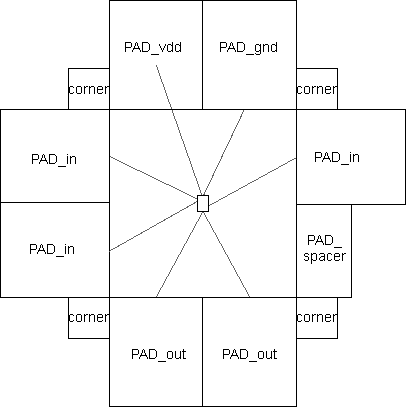 |
This file places 8 pads in a ring (2 on each side) and also places corner "pads" for making bends.
The input pads connect to the 2 input ports "a1" and "a2".
The output pads connect to the 3 output ports "out1", "out2", and "out3"
The power and ground pads connect to the "vdd" and "gnd" ports.
Note that the generator places pad instances, but does not wire them to each other. In order to create a uniform ring of power and ground between the pads, you can use the Auto-router or the Mimic-router (see Section 9-5). |
| Connections between pads and ports of the core cell use Unrouted arcs (from the Generic technology, see Section 7-9). These arcs can be converted to real geometry with the river router. To do this, you must select arcs on one side of the pad frame and use the River-Route subcommand of the Routing command of the Tools menu (see Section 9-5 for more on routing). Because the river router always pushes geometry to the left and bottom, this will work for the left and bottom sides only. To route the top and right sides, you must rotate the entire circuit (select everything and rotate 180 degrees). After routing the top and right (now left and bottom) you can rotate the circuit back to its original position. The finished layout is shown here, fully instantiated. | 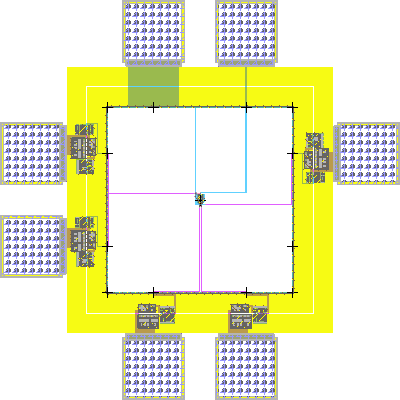 |
 |
Previous |  |
Table of Contents | Next |  |