Chapter 2: Basic Editing
 |
2-2: Circuit Creation
2-2-1: Node Creation |
 |
Node creation is done by selecting a node from the component menu in the side bar (on the left).
Nodes in the component menu are outlined in blue.
After clicking on one of these nodes, click in the edit window to place the node.
If you hold the Control key, the node location will snap to one of the axes.
The location of the cursor is aligned to the nearest grid unit.
This adjustment can be controlled with the
Grid Preferences (in menu File / Preferences..., "Display" section, "Grid" tab,
see Section 4-7-2).
When placing a node, the cursor points to the anchor point of the newly created node.
This is the center (for primitives) or the location of the cell-center (for cell instances).
Cell instances can change their anchor point by moving the Cell-Center node inside of their layout
(see Section 3-3).
When placing a node, but before you click to actually create the node, it is possible to temporarily
switch from node-placement to zoom/pan mode.
This allows you to better select the location of the newly-created node.
To temporarily zoom, type "z", zoom the display, and then type "z" again to finish placing the node.
To temporarily pan, type "p", pan the display, and then type "p" again to finish placing the node.
For more on zooming and panning, see Sections 4-4-1 and
Sections 4-4-2.
Besides basic components, there are special entries in the component menu for creation of additional nodes:
- The "Cell" button displays a list of cell instances that can be created
(see Section 3-3).
- The "Pure" button (only available in layout technologies) lets you place pure-layer nodes
(see Section 6-10-1).
- The "Spice" button (only available in schematics) lets you place Spice primitives
(see Section 9-4-3).
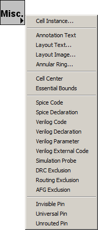
- The "Misc" button has a collection of special objects that can be created.
 |
- "Cell Instance..." brings up a dialog to select a cell instance to place
(see Section 3-3).
- "Annotation Text" places a node that contains only text
(see Section 6-8-1).
This can also be accomplished with the Add Text Annotation command
(in menu Edit / Text)
- "Layout Text..." brings up a dialog to create text from layout nodes
(see Section 6-10-3).
- "Layout Image..." brings up a dialog to create an image from layout nodes
(see Section 6-10-3).
- "Annular Ring..." brings up a dialog to create circular shapes
(see Section 6-10-3).
- "Cell Center" places a node that defines the origin of the cell
(see Section 3-3).
- "Essential Bounds" places a node that defines the corners of the cell's essential bounds
(see Section 7-6-3).
|
- "Spice Code" places a text-only node that will be inserted into Spice decks
(see Section 9-4-3).
- "Spice Declaration" places a text-only node that will be inserted into Spice decks near the top
(see Section 9-4-3).
- "Verilog Code" places a text-only node that will be inserted into the code area of Verilog decks
(see Section 9-4-2).
- "Verilog Declaration" places a text-only node that will be inserted into the declaration area of Verilog decks
(see Section 9-4-2).
- "Verilog Parameter" places a text-only node that will be inserted after the "module" header of this cell
so that a parameter can be defined (see Section 9-4-2).
- "Verilog External Code" places a text-only node that will be inserted outside of any "modules"
so that arbitrary external code can be inserted (see Section 9-4-2).
- "Simulation Probe" places a node that can be used to display simulation results
(see Section 4-11).
- "DRC Exclusion" places a node that hides geometry from DRC examination
(see Section 9-2-3).
- "AFG Exclusion" places a node that tells Auto-Fill Generation to ignore the area
(not currently used, but see Section 9-8-2
for more on Auto-Fill Generation).
- "Invisible Pin" places an invisible-pin node
(see Section 7-6-3).
- "Universal Pin" places an universal-pin node
(see Section 7-6-3).
- "Unrouted Pin" places an unrouted-pin node
(see Section 7-6-3).
