 |
5-2: Constraints |
|
|
5-2: Constraints |
|
|
The first constraint in Electric is the rigid constraint.
When an arc is made rigid, it cannot change length.
If a node on either end is moved, the other node and the arc move by the same amount.
Besides keeping a constant length, rigid arcs attach in a fixed way to their nodes.
This means that if the node rotates or mirrors, the arc spins about,
so that the overall configuration does not change.
Without this rigidity constraint, arcs simply stretch and rotate to keep their connectivity.
The second constraint, which is used only if an arc is not rigid, is the fixed-angle constraint. This constraint forces a wire to remain at a constant angle (usually used to keep horizontal and vertical wires in their Manhattan orientations). For example, if a vertical fixed-angle arc connects two nodes, and the bottom node moves left, then the arc and the top node also move left by the same amount. If that bottom node moves down, the arc simply stretches without affecting the other node. If the bottom node moves down and to the left, the arc both moves and stretches. Rotation of nodes causes no change to fixed-angle arcs unless the arc is connected to an off-center port, in which case a slight translation and stretch may occur. Most IC layout is done with Manhattan geometry. If you suspect that some of your wires have become skewed, use the Show Nonmanhattan subcommand of the Cleanup Cell command of the Edit menu. | 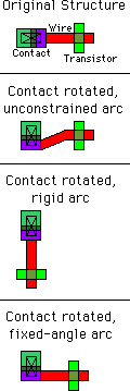 |
The third constraint, also considered only for nonrigid arcs, is slidability. When an arc is slidable, it may move about within its port. To understand this fully, you should know exactly where the arc endpoint is located. Most arcs are defined to extend past the endpoint by one-half of their width. This means that the arc endpoint is centered in the end of the arc rectangle. If the arc is 2 wide, then the endpoint is in 1 from the edge of its rectangle. All arc endpoints must be inside of the port to which they connect. If the port is a single point, then there is no question of where the arc may attach. If, however, the port has a larger area, as in the case of contacts, then the arc can actually connect in any number of locations.
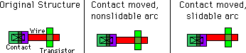
Slidable arcs may adjust themselves within the port area rather than move. For example, if a node's motion is such that the arc can slide without moving, then no change occurs to the arc or to the other node. Without the slidable constraint, the arc moves to stay connected at the same location within the port. Slidability propagation works both ways, because if an arc moves but can slide within the other node's port, then that node does not move. Note that slidability occurs only for complete motions and not for parts of a motion. If the node moves by 10 and can slide by 1, then it pushes the arc by the full 10 and no sliding occurs. In this case, only motions of 1 or less will slide.
Because ports have area, and because arcs end somewhere inside of that area, the actual ending point can vary considerably. If the arc is at the far side of the port, it may protrude out of the far side of the node, causing unwanted extra geometry. You can shorten an arc so that its endpoint is at the closest side of the port with the Shorten Selected Arcs subcommand of the Cleanup Cell command of the Edit menu.
| The last of Electric's constraints is the only one that is not actually programmable by the user. This is the constraint that all arcs must stay in their ports, even across hierarchical levels of design. When a node in a cell moves, and has an export on it, all the ports on instances of that cell also change. The constraint system therefore adjusts all arcs connected to those instances, and follows their constraints. If those constraints change nodes with exports in the higher-level cell, then the changes propagate up another level of hierarchy. | 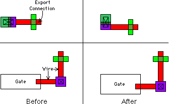 |
This bottom-up propagation of changes guarantees a correctly connected hierarchy, and allows top-down design. Users can create skeleton cells that are mostly empty and contain only exports on unconnected nodes. They can then do high-level design with these skeleton cell instances. Later, when circuitry is placed in the cells, or when layout views are substituted for the skeletons, the constraint system will maintain proper connectivity in all higher levels of hierarchy.
The hierarchical-propagation aspect of the constraint system leaves open the possibility of an overconstrained situation. For example, if two different cell instances are connected to each other with two rigid wires, and one connection point moves, then it is not possible to keep both wires rigid. Electric jogs an arc, converting it into three arcs that zig-zag, to retain the connection. Although connectivity is retained, the geometry may be in the wrong place, causing unexpected changes to the circuit. Users are encouraged to examine the hierarchy to make sure that arbitrary hierarchical changes do not cause undetected damage to the layout.
 |
Previous |  |
Table of Contents | Next |  |