 |
3-12: Automatic View Generation |
|
|
3-12: Automatic View Generation |
|
To convert from IC layout to a schematic, use the Make Schematic View command of the View menu. This builds a new cell using analog schematic parts that are equivalent to the IC components in the current cell. If there is already a schematic view of the current cell, a new version of that view is created.
To convert between different IC layout technologies or from schematics to layout, use the Make Layout View... command of the View menu. You will be prompted for the technology to use for the new cell. If both the current and the new cell are of the Layout view, the new cell becomes a newer version. Conversion between layout technologies is useful when the fabrication process or design rules have changed, but it can only be done within a similar family of technologies, i.e. between CMOS technologies. When converting from schematics to layout, all wires appear as Universal Arcs from the Generic technology. These must be converted to layout manually.
The Make Skeleton View command of the View menu converts the current cell into a new, skeleton view. Skeleton cells contain only the important parts (the nodes with exports and a few others that define the boundary). When skeletonizing, the new cell has information stored on it that points to its original cell, so that it can be restored to its complete geometry later. (At this time, no automatic facilities exist for restoring skeleton cells. Use the Change... command of the Edit menu and select the nonskeleton cell.) Skeletonizing is useful when libraries get to be very large, for they allow entire levels of hierarchy to be abstracted, with their actual contents kept in another library.
A particularly useful view type is icon. The icon cell is used for instances of an associated contents cell, which contains schematics. For example, you may have a cell called "adder{sch}" which contains a schematic. You may then create a cell called "adder{ic}" that contains a circle with a plus sign inside (these are nodes in the Artwork technology). This is then the icon for the layout cell "adder{sch}". Now, if you create an instance of the schematic cell, the icon cell will actually be placed, because it is the symbol that gets used for instances.
To generate an icon cell automatically, use the Make Icon View command of the View menu. Be sure to create all relevant exports before issuing this command, so that the proper icon can be constructed. Note that any export that has its "Body only" attribute checked will be omitted from the icon.
To control the look of the icons, use the Icon Options... command of the View menu. This command lets you place each of the different export types on any of the four sides of the icon.
| You can choose the location of the exports (at the end of the leads, in the middle of the leads, or on the body). You can choose the style of the export text (whether it grows inward, outward). You can choose the technology of the exports ("Universal" uses nodes from the Generic technology which can connect to any arc; "Schematic" uses nodes from the Schematic technology and can connect only to other Schematic arcs). | 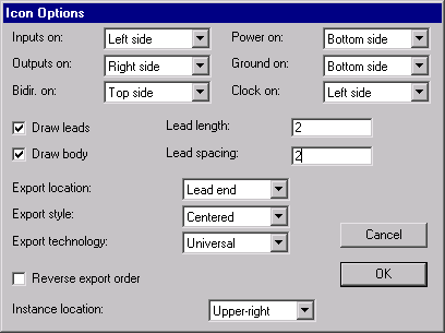 |
You can choose whether or not to draw the leads and the body of the icon. You can set the size and spacing of the leads. Exports are arranged alphabetically around the icon, and you can choose to reverse the alphabetical order. Finally, you can choose the location of the icon instance in the original schematic (when you use the Make Icon View command, it generates the icon and places an instance of that icon in the schematic).
The icon cell is correctly tied to its contents in most respects. If you descend into it (with the Down Hierarchy command of the Cells menu), then you actually find yourself editing the associated contents cell. The Up Hierarchy command properly returns you to the location of the icon instance. Also, the network consistency checker and the simulators correctly substitute the contents whenever an icon appears. In order for this to work, however, all exports in the contents cell must exist with the same name in the icon cell (with the exception of those that are marked "Body Only").
The Make VHDL View command of the View menu converts the current cell into a VHDL textual description. All subcells used in the current one are also converted. By default, the VHDL is placed in cells with the "vhdl" view. However, by unchecking the "VHDL stored in cell" item of the VHDL Options... dialog (in the VHDL Compiler subcommand of the Tools menu), the VHDL will be placed in individual disk files. Recheck the entry to place VHDL in cells again. See Section 9-10 for more on Electric's VHDL facility.
 |
Previous |  |
Table of Contents | Next |  |