
9-4-4: Special Spice and Verilog Nodes
Chapter 9: Tools
|
9-4: Simulation Interface 9-4-4: Special Spice and Verilog Nodes |
|
For both Spice and Verilog, you can place special nodes in your circuit that augment the generated deck. Spice even has a predefined set of these nodes, available from the "Spice" entry in the component menu. A second set, called "SpicePartsS3", is tailored towards Spice3 (use the Spice/CDL Preferences in menu File / Preferences..., "Tools" section, "Spice/CDL" tab, to switch to this set). There are no Verilog nodes in the current release of Electric. Users who define new nodes for Spice or Verilog are encouraged to share these with the entire community by contacting Static Free Software.
Users can define their own Spice or Verilog nodes by creating new icon cells. The icon cell should have:
| To explain the format of a template, a DC Voltage Source primitive is used as an example. Graphics is placed to describe the look of the symbol (a "battery" look). Exports are created at the top and bottom of the battery with the names "plus" and "minus". | 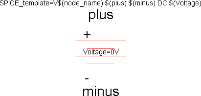 |
A single parameter is defined called "Voltage" with a default value of "0V".
Finally, a Spice template is created that has the string:
V$(node_name) $(plus) $(minus) DC $(Voltage)
This string contains substitution expressions of the form $(SOMETHING)
where SOMETHING can be an export, a parameter, or "node_name".
In this example, $(node_name) will be replaced with the name of the voltage node;
$(plus) will be replaced with the net name attached to the positive export;
$(minus) will be replaced with the net name attached to the negative export;
and $(Voltage) will be replaced with the voltage value specified by the user.
When defining technologies, it is possible to place Spice templates onto primitive nodes
(see Section 8-6).
These templates can make use of two additional substitution expressions:
$(width) and $(length) which access the size of the node.
 |
Previous |  |
Table of Contents | Next |  |