
7-5-2: Multipage Schematics and Frames
Chapter 7: Technologies
|
7-5: Schematics 7-5-2: Multipage Schematics and Frames |
|
Multipage schematics are implemented in Electric by having each page map to a different area of a vast schematic cell. To create one of these multipage cells, use the Make Cell Multi-Page command (in menu Cell / Multi-Page Cells). You will then be editing page 1 of the multi-page schematic.
You can add pages to the current multipage schematic with the Create New Page command (in menu Cell / Multi-Page Cells). You can delete the current page with Delete This Page. To advance to the next page, use Edit Next Page.
Older versions of Electric implemented multipage schematics with different view types ("p1", "p2", ...). If these views appear instead of proper pages, use the Convert old-style Multi-Page Schematics command.
As a graphical aid to schematic design, frames can be displayed in a cell by using the Cell Properties... command (in menu Cell). Multi-page schematics require a cell frame on every page, but their presence is optional in other cells.
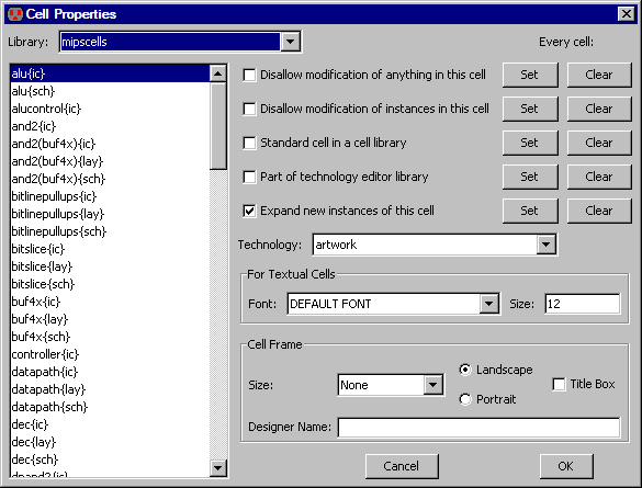
The frame size can be "Half-A", "A", "B", "C", "D", and "E". The frame can be horizontal (landscape) or vertical (portrait). You can choose to display a title box in the lower-right corner. The designer name can also be set for each cell.
Besides the designer name, cell frames have a company name and a project name. These values are not set for each cell, but instead are preferences that are set for each user. Individual libraries can override these defaults as well.
| The Frame Preferences (in menu File / Preferences..., "Display" section, "Frame" tab) lets you set all of these defaults. Note that the designer name is taken first from the cell, then from the library if the cell does not set a value, and finally from the general default if the library and cell do not set a value. | 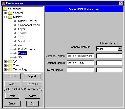 |
 |
Previous |  |
Table of Contents | Next |  |