
4-7-2: Aligning to a Grid
Chapter 4: Display
|
4-7: Grids and Alignment 4-7-2: Aligning to a Grid |
|
When moving or creating circuitry, the cursor location is snapped to a grid so that editing is cleaner. This snapping is controlled by the alignment options (which are not necessarily the same as the grid options).
The Grid Preferences (in menu File / Preferences..., "Display" section, "Grid" tab) presents a dialog in which alignment values may be set. For example, if the grid spacing is 2x3, and the alignment is 0.5 x 0.5, then there are up to six different positions for placement inside a displayed grid rectangle.
There are 5 alignment values, all settable in the dialog. The current alignment setting is shown in the toolbar (see Section 2-4-1).
| Note that these alignment values are also used to determine the distance moved by arrow keys. You can change the alignment setting with the commands Grid Alignment 1 (largest), Grid Alignment 2, Grid Alignment 3, Grid Alignment 4, and Grid Alignment 5 (smallest) (in menu Edit / Modes / Movement). | 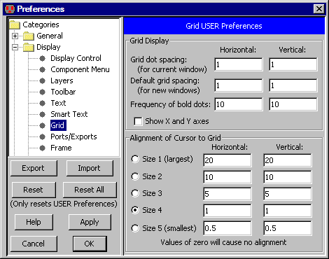 |
You can also change the alignment by a single step by using the commands Make Grid Larger (attached to the "f" key) and Make Grid Smaller (attached to the "h" key).
The Align to Grid command (in menu Edit / Move) cleans up the selected objects by moving them to aligned coordinates. This is useful for circuitry that has been imported from external sources, and needs to be placed cleanly for further editing.
 |
Previous |  |
Table of Contents | Next |  |