 |
9-12: Logical Effort |
|
|
9-12: Logical Effort |
|
When the Logical Effort tool runs, it annotates each digital schematic gate with a fanout ratio that can be used to size the transistors inside of that gate. It is up to the designer (or potentially some other tool) to use this information in the actual IC layout.
The Logical Effort tool has two functions: path analysis and whole-cell analysis.
In path analysis, the user must select two points in the circuit that define the ends of a path. Selection of these two points is done by clicking the selection button over the first point, and then using the toggle select button on the second. Capacitive loading on the ends of the path can be specified by creating Load objects and parameterizing their capacitance. These Load objects are created with the New Arc Load subcommand of the Logical Effort command of the Tools menu. To do the path analysis, use the Analyze Path subcommand, which determines the optimal fanout for each step in the path. Besides marking each gate with a fanout value (shown in the form of "h=2.5"), intermediate capacitance values are displayed along the path.
In whole-cell analysis, the Logical Effort tool iteratively applies capacitive loading constaints until the circuit fanout is determined. Once again capacitances can be set with the New Arc Load subcommand of the Logical Effort command of the Tools menu. Then, the Analyze Cell subcommand iterates over the circuit, attempting to find ratios that are less than or equal to the maximum stage gain (initially 3). As with path analysis, each gate is marked with a fanout value, and intermediate capacitances are displayed in the circuit. To change the maximum stage gain that is used in whole-cell analysis, use the Logical Effort Options... subcommand of the Logical Effort command of the Tools menu.
|
Besides setting the maximum stage gain for whole-cell analysis, the Logical Effort Options... subcommand of the Logical Effort command of the Tools menu allows other settings. You can request that intermediate capacitance values not be displayed after analysis, and you can request that the analyzed nodes be highlighted. Also, you set the wire ratio for each arc (a value used in load computation). | 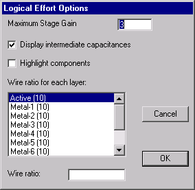 |
It is possible to override the default calculation of the logical effort on a single node by using the Set Node Effort... subcommand of the Logical Effort command of the Tools menu. The value entered is shown in the form "g=2" on the node, and is used in subsequent analysis.
An example of Logical Effort can be found in the "samples.txt" library (you can read the library with the Readable Dump subcommand of the File menu). Edit the cell "tool-LogicalEffort" and use the Analyze Cell subcommand on it.
There are three commands that analyze the circuit as an aid to doing Logical Effort. The Estimate Delays subcommand computes load factors for every network in the cell. This information is not generally useful, and is provided for future Logical Effort analyses. The Show Network Loads subcommand lists every network in the current cell, showing the wire length, load, and other information. The Analyze Network subcommand shows a detailed analysis of the currently selected network, including the area and perimeter information for each layer, as well as load information.
 |
Previous |  |
Table of Contents | Next |  |