Chapter 1: Introduction
plug
1-11: Schematics Tutorial
1-11-5: Schematics Tutorial: Multi-Input gates and Negation
plug


One aspect of the And, Or, and Xor gates that you will notice is that their left side (the input side) can accept any number of wires. To see this in action, place one of these components in the cell. Then repeatedly select its left side and use the right button to draw wires out of it. Each wire will connect at a different location in the input port, and once the side fills with arcs, it will automatically grow to fit more. Note that the vertical cursor location along the input side is used to select the position that will be used when a new wire is added.

Figure 1.14

To negate an input or output of a digital gate, select the port or the arc and use the Toggle Port Negation command (in menu Edit / Technology Specific). With this facility, you can construct arbitrary gate configurations.
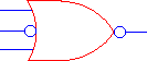
Figure 1.15


Prev Previous     Contents Table of Contents     Next Next