 |
1-10-3: IC Layout Tutorial: Highlighting |
|
|
1-10-3: IC Layout Tutorial: Highlighting |
|
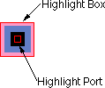 | A highlighted node has two selected areas: the node and a port on that node. Note that the transistor is highlighted in the previous example, and the contact is highlighted in the example here. The larger selected area covers the node, and it surrounds the "important" part (for example, on the Transistor, it covers only the overlap area, excluding the tabs of active and gate on the four sides). The smaller selected area is the currently highlighted port (there are four possible ports on the transistor, but only one on the contact). |
To highlight a node, use the left button. The node, and the closest port to the cursor, will be selected. After highlighting, you can hold the mouse button down and drag the highlighted object to a new location. If nothing is under the cursor when the selection button is pushed, you may drag the cursor while the button remains down to define an area in which all objects will be selected.
Another way to affect what is highlighted is to use the shift-left button. This button causes object highlighting to be reversed (highlighted objects become unhighlighted and unhighlighted objects are highlighted).
The shape of the highlighted port is important. Ports are the sites of arc connections, so the end point of the arc must fall inside this port area. Ports may be rectangles, lines, single points (displayed as a "+"), or any arbitrary shape. For example, when the active tabs of a transistor are highlighted, the port is shown as a line.
 |
Previous |  |
Table of Contents | Next |  |